 01-24-2019, 09:00 PM
|
#16 |
|
Join Date: Oct 2018
Posts: 74
|
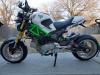
The aliexpress package arrived!
The was packaging on-par with 90% of the other orders I've had arrive from China. Everything was there and everything I've tested works. I have yet to test fuel pump because I self imposed a rule of no fuel indoors (gas tank and carb are out in the garage). The CDI that came has a green LED next to the 4+2 pin connector. I'm assuming and hoping that LED blinks when the CDI gets the signal to fire the spark coil. I'm also hoping that the CDI has either no ignition advance or fixed ignition advance. That will make troubleshooting and diagnosing problems much easier. The ECU connects to the software provided and all of the readings look good. The wires are potted into the case, BUT! it is a soft re-enterable potting compound similar to pure silicone or liquid electrical tape (not like the rock-hard kind that is used on CDI boxes) AND the case is screwed together, not glued or ultrasonically welded! I think my chances of at least getting the case open without destroying the PCB and/or case in the process are good. In one of the pics you can see a size comparison to a microsquirt and its harness. The MS uses better, larger, more, and labeled wires. Of course, it's not really a comparison between the two as the MS can control up to 8 cylinders. I'm jumping around between testing out the software, mentally running wires, and looking for places to mount the ECU, relays, fuses, fuel pump, spark coil, oil cooler, you get the idea. Before I start going wild cutting, crimping, soldering, and swearing, is there anything anyone wants to know about the EFI kit? Honestly, as much as this project is about converting my engine to EFI, I see that there are a lot of people on this forum and all over the internet that would like to get a kit like this, but aren't sure if it will work at all, if it will work with their particular engine and bike. I want to share as much knowledge about this kit and project as I can so maybe someone will come across this thread or one like it, read it and get the information that they were searching for, or be encouraged to try out a project on their own and have all the support that this forum and most of the other forums around the internet. Demon cat (Nollie) says FEED ME! Last edited by glavey; 01-25-2019 at 12:03 AM. |

|
|
01-26-2019, 12:01 AM
|
#17 |
|
Join Date: Oct 2018
Posts: 74
|
Didn't do much today, but made some discoveries, both good and bad, and made some mental planning headway.
Discovery #1 - ...this one is all my fault. The flange on the throttle body doesn't line up to the 190's manifold bolt holes. I checked the 125's manifold and sure enough it bolted up and fit perfectly. I should have asked for the clamp mount TB. Heck, the 190 even came with a flange-to-clamp adapter for the carb! Oh well, mistakes just mean you learned something new. I can still drill and tap new holes in the 190 manifold, so all is not lost. Discovery #2 - The throttle cable that came with the bike, the choke cable that came with the bike, the throttle cable that came with the 190, and the throttle cable that was harshly salvaged from my scooter either don't have enough cable throw or don't have the correct barrel-end. I kinda expected to have to do something to the throttle cable since I'm going from a carb to TB. Tomorrow I will probably trim the sleeve on one of the throttle cables carefully with a dremel and find some way of making a crimp/termination on the sleeve end. Discovery (more like a dream project) #3 - If I put an ABS-style slotted rotor on both wheels, put new rearsets on with a sensor in the linkage to the shifter, and convert to ride-by-wire, I could have a crom with traction control, launch control (kinda pointless on a bike), power modes, ABS, and quick-shifting up and down with auto-throttle-blip. I think I just wet myself. Activity #1 (and only) - Wired the 190 stator output into the 125 wiring harness. The black/red wire is/was the power supply for AC-powered CDIs. The one that came with the aliexpress kit is DC-powered. I will be keeping the 125 harness 90% as it is, most of it is lighting-related. I'll run the aliexpress-ecu/microsquirt harness separately. I'll start out using the aliexpress one to see if it is a viable option for a cheap EFI kit. Then I'll go and wire in the microsquirt harness, which will take considerably longer than putting in the aliexpress one. I may even have to cannibalize the aliexpress harness for all the connectors, but not before I at least try and crack the case open and see what is in there. |
|
|
|
01-26-2019, 01:56 AM
|
#18 |
Join Date: Aug 2018
Posts: 286
|
Moving right along. Very good information.
__________________
2018 BD125-8-x21rs ZS190/Genuine PE28 Kepspeed GP1 Exhaust Protaper se x110 bars/grips 1/4 MotionPro throttle Kepspeed Braced swingarm Chimera rear hub assy Grom Intergrated tail light Superlite Sprockets 17/32 custom made from Japan Chimera Swing Arm Bolt RK MXZ Chain #420 All Balls wheel bearings Motodynamic fender eliminator Coremoto ss brake lines Composimo 2.5 lower link Grom Calipers-w/ebc pads/rotors Michelin tire 140&120 13x4/13x7 fatties Grom forks |
|
|
|
01-26-2019, 10:28 PM
|
#19 |
|
Join Date: Oct 2018
Posts: 74
|
Successfully shortened the sleeve on a throttle cable using a dremel without nicking the cable! Throttle grip now feels just like it did with a carbie. Turns out I will need to buy the intake manifold rotator/adapter from steady garage. I could use a ~1/4" sheet steel spacer instead, but cutting through that with hand tools... nope.
Terminated all the remaining wires from the engine, and started mounting the fuse box and main power relay. Instead of the ignition switch having all of the current from the battery go through it, I decided I would wire in a main relay and use the ignition switch to toggle the relay on/off. It just seemed like a good thing to do. Plus, the fuse box is literally right below it, so wiring is a bit easier. One bad thing, though. The fuse box and main relay took up all of the half-sandwich-sized-storage underneath the seat. I can still tuck the little tool pouch and tools that came with the bike in-between the frame and the rear plastics. There is going to be one main fuse between the battery and the main relay, then, from the fuse box, there will be separate fused circuits for lighting/CDI/dashboard/controls, fuel pump and heated o2 sensor on a shared relay circuit, and the injector. I may not be able to use ALL of these relays with the aliexpress ECU, as I haven't yet tested to see if the injector and/or the fuel pump are high-side or low-side switched. I confirmed that I have the neutral correctly wired when I did a quick electrical test before I started gutting the 125's harness. There is a video on youtube that shows/tells you to connect the green wire with the red stripe coming from the 190 engine to the red wire on the former-gear-position-connector in the top-right corner. This is partially correct. The wire in the top-right corner of the gear connector is red with a green stripe. This is the wire you want to connect the neutral wire to. The wire in the bottom-right corner is red with a white stripe, so be careful to connect to the correct one. I'm sure the guy in the video just didn't see the green stripe on the wire at first, I didn't either. Part of wiring in the main relay is connecting to the switched +12v (black) wire in the harness. There was a black wire on the security/alarm connector that was switched +12v, but the wire was such a small gauge, I couldn't in good conscience have all of the current going through that wire. I peeled open the harness and searched for the spot closest to the relay that had a solder/crimp joint on the black wire so I could run a thicker, beefier wire directly to that point. As you can see in one of the pictures, the crimp is about as good as you would expect from china. Serviceable, but just barely hanging in there. I flooded the whole crimp and the new bigger wire with solder for a better connection. The relay for the fuel pump/o2 sensor heater will have to be somewhere besides the under-seat area; I'm using harnesses with pigtails for the relays and they about double the room a relay takes up. |
|
|
|
01-28-2019, 12:04 AM
|
#20 |
|
Join Date: Oct 2018
Posts: 74
|
Finished the main relay wiring, had to run a power wire into the 125 harness for the same reason I did yesterday - wire gauge was too small. Confirmed the relay works as it should by testing everything except the horn. With as many of the lights turned on as I could, I measured roughly 500 mA through the lighting circuit. I don't know how much current a horn uses and I don't want to pop a fuse every time I honk at someone, budgeted another 500 mA for it. So at max that circuit should pull about 1 A, so I think a 2 A fuse will be sufficient.
I placed and semi-permanently mounted the aliexpress ecu and began running wires, crimping connectors, finding wiring routes, etc. I should only need to splice into/modify 6 wires on 3 connectors; power/ground for the fuel pump, injector, and o2 sensor heater. I was looking online at vacuum-referenced fuel pressure regulators - youch! Unless you want to go with a REALLY cheap $15 regulator that has poor reviews, the cheapest ones start at around $100. The manual for the microsquirt does say that a vacuum-referenced regulator is and I quote, "Essential". I'm positive the people who designed the ECU and wrote the manual for it have done at least hundreds of EFI installs between all of them. This is my first one. I'm going to trust them. I took a closer look at the little regulator/pump assy from the aliexpress kit. There are two holes on either side of the metal diaphragm housing and one on top. I think if I seal the two side holes shut and epoxy or JB weld a hose barb on the top one, I could turn this into a vacuum-referenced regulator! Even if it doesn't work, I'll still have the top hole open so it should still work as a fixed pressure regulator. The two next big-ish things to do are to drill the holes in the 190 manifold for the TB, and get the bung welded on the exhaust. I'll definitely get the former done before the latter as I just have a puny little 80 A buzz box and all of my experience in welding adds up to about 10 crappy welds done on sheet steel. Also, there is a snow storm a-coming tonight and I expect to be slow-blowing a foot of snow tomorrow or the next day. I'm also uploading a copy of the tune that was on the aliexpress ECU when I received it, I changed nothing on it. You can view it with the software posted here, I'm nut sure if I have a high enough post count that external links won't look like spam. When you start the software for the first time, go to File -> Offline. The software is constantly looking for a connection to an ECU, slowing down the program and it will keep looking until you go click offline in the file menu. |
|
|
|
01-28-2019, 10:42 AM
|
#21 |
|
Moderator

Join Date: Oct 2016
Location: Houma, La.
Posts: 11,533
|
Thanks for posting such a detailed step by step.
 I'm been following this one. I'm been following this one.
__________________
2023 Lifan Lycan 250 Chopper 2023 Venom Evader 2022 Lifan KPX250 2020 Kawasaki Vulcan S 2004 Honda ST 1300 2016 Black Hawk 250 (sold) Keihin PE30 carb,125 main,38 slow.Pod filter,ported & decked head 10:1 CR,Direct Ignition Coil,15/40Sprockets,NGK DPR8EIX-9,De-Cat,Dual Oil Cooler,Digital Cluster 2016 Cazador180 XL 2014 Coolster150 JerryHawk250.com My YouTube Channel |
|
|
|
01-28-2019, 12:51 PM
|
#22 |
|
Join Date: Oct 2018
Posts: 74
|
No problem, I'm just glad I am able to do this at all. If you or anyone else wants more info on anything or if I didn't explain something well enough (I'm a scatter-brained airhead with limited attenti- SQUIRREL!) go ahead and ask, I'll be happy to try and explain further.
|
|
|
|
01-29-2019, 01:22 AM
|
#23 |
|
Join Date: Oct 2018
Posts: 74
|
I think I found a very good mounting location for the fuel pump. I took the starter solenoid off the two mounting tabs and out of the rubber holder, cut the bottom flange off of the rubber holder and slid it over the fuel pump. Nearly a perfect fit. I moved the starter solenoid to the tab above the rear brake fluid reservoir. I had a spare rubber holder from the extras that came with the 190. The pump is a little tight between the tabs on the frame, but that is better than too loose. I'm still going to secure it with some zip ties.
I drilled and tapped two new holes in the 190 manifold for the TB mounting points. I wanted to use a metric thread so I could keep almost all things of the hardware on the bike metric, but the closest I had was a 1/4-20 so I went with that. The holes and threads are a wee bit off-center, but still very usable. Even if they end up too crooked or I strip the threads, I can just use a nut on one side. I ordered the intake clocking flange from steady garage. It seems almost mandatory to have some way to either raise and/or rotate the intake if you want to use the flange TB from aliexpress. You might be able to squeeze the clamp TB in, but it will be difficult. I still might attempt to put the injector directly into the manifold on the flat spot... I tested some of the wiring on the aliexpress harness - the heater circuit for the oxygen sensor is directly connected to battery voltage and ground, no control from the ECU. The fuel pump is connected to battery voltage and switched to ground via the ECU. This means I can wire two relays to both turn on when the fuel pump is supposed to run, while still having two separate and fused circuits. So whenever the fuel pump is running, the o2 sensor will have its heater on. I can turn off/disable the o2 heater if I find that it is drawing too much current or the exhaust is heating the sensor enough/too much. I might wire the CDI to turn off whenever the fuel pump is off as well, it seems safe to disable the ignition when it isn't needed. |
|
|
|
01-29-2019, 11:41 PM
|
#24 |
|
Join Date: Oct 2018
Posts: 74
|
The wideband sensor and controller arrived as well as some exhaust gaskets. I'm glad I haven't got around to getting the o2 sensor bung welded in yet, because the wideband sensor uses a much larger diameter thread than the narrowband that came with the aliexpress kit. I'm going to be starting with the aliexpress ECU and hardware so I wanted to start with the narrowband sensor as well to keep my experiences as similar as possible to someone who just ordered the aliexpress kit and nothing else. However, since the wideband and narrowband do not the same thread size/pitch, I am going to use the wideband from the start, but I will be using the simulated narrowband output from the controller to emulate the experience I or someone else would get if using the narrowband sensor that came with the aliexpress kit.
The exhaust gaskets are nothing special, they look like standard metal crush-type gaskets. After I read this post by someone who was using the same kit as I am, I knew before I even ordered it that I would need to run a relay for the fuel pump, but I didn't realize just how anemic the power wires for the pump would be and are. I had to cut and discard the waterproof connector for the fuel pump on the harness and on the pump itself. I now have power going straight from the fuse box to a relay, from the relay directly to the pump, from the pump directly to the same grounding point as the battery negative is connected to. I'll be doing the same with the heater for the oxygen sensor. As I said in my last post, I wanted to put the CDI/ignition system on a relay as well, but unless I start drilling into the frame, I am out of room to mount another relay. I also discovered that the high-pressure outlet on the fuel pump isn't meant for connecting directly to a fuel hose, it is a quick-connect fitting. You can see here that the single barb connector is for the quick connect and the standard-looking barbs are for hoses. I might use a quick-connect as the project gets closer to the first-start-up phase, but since I don't even have the fuel tank on the bike, I'll worry about that later. |
|
|
|
01-30-2019, 12:23 PM
|
#25 |

Join Date: Mar 2009
Location: Sardis, BC, Canada
Posts: 25,977
|
Too bad about the pump power wires. Looks like they took the time to use a Weatherpak-style connector. The good news is that you can make new ones for cheap.
__________________
Weldangrind "I figure I'm well-prepared for coping with a bike that comes from the factory with unresolved issues and that rewards the self-reliant owner." - Buccaneer |
|
|
|
01-30-2019, 09:56 PM
|
#26 |
|
Join Date: Oct 2018
Posts: 74
|
Yep, already priced out replacements for whenever the EFI harness gets final and permanent. I had to cut half of another connector off today, this time it was the harness-half of the oxygen sensor connector. The aliexpress harness had the same... I'm guessing 20 gauge wire for the o2 sensor heater. Not enough for me to feel comfortable. I wired the wideband controller directly to the relay that shares the same input as the fuel pump, so whenever the fuel pump is running (only when the engine is running, or for 2 seconds on initial startup), the o2 sensor heater will be able to turn on. You can kind of see the two black/white wire pairs connected together in one of the pictures, that's the fuel pump power from the ECU wired to trigger both relays.
Here is a quote from the wideband sensor user manual: "Do not install the Lambda Sensor in such a manner that the unit is powered before your engine is running. An engine start can move condensation in your exhaust system to the sensor, if the sensor is already heated this can cause thermal shock and cause the ceramic internals inside the sensor to crack and deform." Also; "While the Lambda Sensor is in an active exhaust stream, it must be controlled by Spartan Lambda Controller. Carbon from an active exhaust can easily build up on an unpowered sensor and ruin it." So I can either not have any o2 sensor, or I have to have a powered o2 sensor. Kinda sucks, but I get it. The wideband controller has separate grounds for the electronic signals and for the heater. Since I can't (yet) directly access the connections directly on the ECU board, I had to settle for the ground wire that was for the original o2 sensor connector. I placed the wideband controller on the right side of the frame, opposite the voltage regulator/rectifier. There aren't any mounting points on the controller, its just a PCB with wires coming out of one end and a connector on the other, covered with thick heat shrink tubing. At the moment, it is temporarily zip-tied in place. I want to either secure it with at least one more zip tie or move it somewhere else on the bike (there aren't many more places) where it can be more securely attached to the frame. The big yellow cable with red tape on it is an old ethernet cable all but two wires taken out of it. The wideband controller has an output for an LED that will tell you through the speed of light blinks or by steady operation if the sensor is too hot, too cold, or goldilocks. The amount of heat contained in the exhaust is going to change based mostly on throttle position, so it may be too cold at idle and good at the top end, or good at idle, but bad at the top end. Being able to monitor whether or not the sensor is "happy" is a good thing to me, especially since I am going to basically be making an educated guess as to the distance from the exhaust port the sensor is going to be. I have heard plain vehicles should have them placed around 2 feet from the port, some say closer, some say further away. I have read ONE anecdote from here that says, "The more cylinders that feed the exhaust pipe, the more heat goes to the sensor. It’s possible to locate a sensor 300 mm (12”) from a single cylinder runner pipe (such as on an air-cooled motorbike), although we would suggest a little further back (500-600 mm = 20-24”) if the sensor is under bonnet." I think I'll try right around 12 inches from the port, maybe 18; the exhaust header and the o2 sensor are going to be exposed to fast moving cool air 99% of the time. If that doesn't work, I'll just have to get another bung welded on elsewhere. I do have one small concern about the exhaust and wideband - from the document I linked to earlier: "If you have any kind of exhaust leak out of the exhaust pipe then it’s also possible there is a leak into the exhaust pipe too. Eliminate all exhaust leaks without resorting to sealing compounds as these can often damage the sensor through silicon contamination. Even small leaks may result in meaningless lambda readings..." The exhaust system I bought is connected together with slip joints. I don't see a way those joints won't leak if I don't use some sort of sealant. In the picture of the right side of the bike, you can get a better idea of the location of the fuel pump and the wideband controller. I left myself plenty of extra wire connected to the controller in case I have to move it to a different location. Not pictured is another 6 FEET of cable that I cut off of the controller. I'll be saving that wire for when (if) this project nears completion and I'm wiring up everything for the final time. You might not be able to tell, but in the second picture it shows the area between the reg/rec and the relays is just filled with wires. I am going to try my best to keep most of the wiring running along or just below the frame, and the small area between the ECU and relays is going to be for all of the fuel lines, filters, connections, gauges, etc. I'm really trying to think ahead as far as I can, and doing this project during the winter has been a blessing in disguise - normally on any project I'm working on something I really love (no exception here) so the whole time I'm working/building/modding/fixing/fixing previous fixes, I'm not able to USE the thing I'm working on. Right now, If I even tried to start the bike, I'd freeze my nuts off outside before it warmed up. Knowing that I'm not wasting any valuable riding time trying to get everything as good as I can get it is great. The intake manifold rotator should arrive tomorrow, and once that is installed, there isn't really much to do except plumb fuel lines, tidy up the rat's nest wiring, test what can be tested without go juice, and maybe sit on it for a few hours making vroom vroom noises. Oh, and I want to add some reflective tape/stickers/reflectors so that from 3, 6, 9, and 12 o'clock, there are at least 3 reflective items that can be seen with a rider on the bike. I will probably slow down the posting once I've done all I can do indoors. I'll probably continue to check daily for questions and what-not. |
|
|
|
01-31-2019, 12:55 PM
|
#27 |
|
Join Date: Mar 2009
Location: Sardis, BC, Canada
Posts: 25,977
|
IIRC, blue Permatex is sensor-safe.
I appreciate your writing style, and I had a good giggle at the Goldilocks comment. I'm stealing that one. 
__________________
Weldangrind "I figure I'm well-prepared for coping with a bike that comes from the factory with unresolved issues and that rewards the self-reliant owner." - Buccaneer |
|
|
|
01-31-2019, 09:49 PM
|
#28 |
|
Join Date: Oct 2018
Posts: 74
|
Thanks for the info and the kind words, I bought some permatex ultra copper right after I started this project, but wasn't aware it was sensor-safe. Well, there goes that worry... for now.
The intake clocking flange arrived and fits beautifully. At first I tried mounting the manifold pointing out toward the right side of the bike, but either the throttle cable mounting point hit the bottom of the frame, the clutch cable was pushing and rubbing on the injector housing, or the air filter would have gotten in the way of where the oil cooler will live. Right now I have it pointing out the left side, perpendicular to the bike frame and engine. The wires will be tied up to the frame on either the left or right side, so they won't get in the way of the throttle operation. The throttle cable itself does sit at an odd and possibly uncomfortable position; it exits the throttle body pointing about... 2'clock, but then goes through a 90 degree bend and points downward toward the cylinder head. It's difficult to explain, you can kind of see what I mean in one of the pictures. Everything else has plenty of room around it, the idle air screw, the worm-drive clamp for the air filter, the fuel injector hose barb and electrical connector. The air filter even clears the red side-fairings. A note on the air filter though - as you might be able to tell in one of the pictures, the air filter that comes with the 190 will not fit on the TB from aliexpress, the fiter is too big. The filter size that the VM22 uses DOES fit, I think it is 38mm, but I'm not sure. I'm going to be using the filter that I used with the VM22 when it was on the 125. The stock bolts that are used to mount the intake manifold to the intake port are too long to use with the clocking flange, well one of them will be. One of the bolt holes on the intake manifold has more distance in the manifold to go through. I probably didn't explain that very well. What happens is one of the bolts will fasten as expected, but the other one bottoms out on the cooling fins before clamping the manifold down. No big problem, just grind and cut away some of the bolt and it'll be right. I bolted the coolant (cylinder in out case) temp sensor to a hole near the bottom of the cylinder jug that was already threaded. I assume there mounting points are for those chin fairings I see on some of the croms. I'm going to wrap the wire in something to protect it from the heat and abrasion of rubbing against the engine case. Since I had already run a cable up to the dashboard area with an LED indicator for the wideband, I thought I might as well run the LED indicator that the ECU has up there as well. Not much to explain here; I just lengthened the wire that the LED was connected to. I connected all the electrical connectors except for the fuel pump and the wideband controller, connected a battery to the bike, connected a laptop to the ECU, and turned on the switch. Woo Hoo! No magic blue smoke! MAP, manifold temp, cylinder temp, throttle position, battery voltage, and both relays connected to the fuel pump enable signal worked and displayed correct readings. One word of note that I should mention - make sure the wire that connects the CDI to the ignition coil is connected to the coil and not disconnected or touching anything that is grounded to the bike's battery. Sweaty hands, dry air, and high voltage mix together with... shocking results. If you touch or hold the output from the CDI while grounded, you will become the coil and spark plug. Another way to say this is don't include yourself in the ignition circuit! There are only one or two somewhat big things still to do, but lots more tiny things to do and some things to buy or think if I really need to buy them. So far I have to:
Within the next few days is the time I'll start to wind down on the posting because there won't be much to post about, but rest assured I want this project to continue and be completed as much as you. |
|
|
|
02-02-2019, 06:25 PM
|
#29 |
|
Join Date: Oct 2018
Posts: 74
|
Done:
Tomorrow will probably be oil cooler install and oil change. |
|
|
|
02-04-2019, 06:22 PM
|
#30 |
|
Join Date: Oct 2018
Posts: 74
|
I tidied up the wiring and somewhat-finalized the location of the wiring harness, connectors, wire and cable routing, etc. The clutch cable, as it was with the 125, had to be routed between the red fairings and the white gas tank fairing. I tried my best to get every wire or connector that would be just sitting against anything else in a corrugated cable sleeve, spiral strain relief, wrapped in electrical tape, or zip-tied securely in place so the vibrations from the engine won't abrade through the wire's insulator. Everything seems to fit inside the fairings so far. The oil cooler mounted with only one little issue. I used the bracket that the horn was originally mounted to for the oil cooler, I remounted the horn on the bottom triple clamp. If I bolted the oil cooler on in the order of oil cooler -> mounting bracket -> nut; then the bottom triple clamp would hit the sides of the cooler at full lock in either direction. I ended up bolting it up in the order of mounting bracket -> metal spacer -> oil cooler -> nut. It now clears the triple clamp with about a 1/4" on either side. I changed the oil. Not much to say here. I used 700mL of valvoline premium blue 8600 es 15w-40. 600mL is the usual oil change capacity (as read from a daytona anima 190fdx engine manual), 700mL is the full capacity, but the oil cooler and lines are empty. I'll check the levels after I get a chance to start the engine, or at least turn it over. I don't know if I mentioned this in a previous post, but one thing you have to do with a swap to the 190 is cut/grind away one of the rear brake arm return spring mounting tabs. I did that plus about another 1mm from the arm right where it would touch the case. I cleaned and painted the area I ground down with some "toyota white" touch up paint I had. I hadn't thought of this until a few days ago, with the ECU directly controlling the CDI and thus the entire ignition system, the kill switch on the handlebars isn't going to do anything. I looked online to see how the kill switch is usually wired up and it was different than what I though it was going to be, in a good way. I thought that the kill switch 1. interrupted the signal from the CDI to the ignition coil and 2. did that by just breaking the connection from those two points. It turns out that the kill switch grounds out one lead of the trigger coil inside the stator cover, and since the other lead is grounded through the engine, there can be no more signal from trigger coil, no more spark. This meant that I just had to make a "Y" fitting for the blue wire that was coming out of the engine's stator cover, one end going to the ECU as it was before and one going to the blue wire's terminal in the wiring harness' stator connector. Another thing that I assume uses that signal is the tachometer in the dashboard. I'd hate not having that. In a previous post, I said the exhaust I bought for the bike would just barely clear the starter motor. I was wrong. It does NOT clear the starter motor. I see a few options here. 1. Get a piece of exhaust pipe welded to the part that goes in the exhaust port on the engine. This would be difficult because any welding/automotive/bike shop probably won't have the size and thickness of pipe I need in stock, and they would, unless they can decrease the size of an exhaust pipe, be butt-welding two pieces together and they'd have to weld it from the inside. 2. Cut the exhaust at a given location and weld in an extension. If I, or they, can cut the exhaust square enough, the ends of the extension could be expanded so there wouldn't have to be a butt-joint, but a (I think) lap joint. I would have to get the exhaust painted or coated again if I did that. 3. Use the old exhaust from the 125, somewhat gutted or a hybrid franken-pipe with the muffler canister part from the new exhaust on the old pipe. 4. Buy a new exhaust and eat the stupid tax. 5. Heat and bend the exhaust pipe. If worse comes to worst... 6. Remove the electric starter, use the kick starter (I'd have to grind away some of the right rear set for fitment). I have heard that the starter chains on these engines have more-common-than-it-should-be rate of failure. Struggling to get the bike started while tuning it to even be able to start isn't something I'm looking forward to... Decisions, decisions... Oh, and I might have to remove the right passenger's footpeg to clear the muffler. No big deal; I'm never going to ride two-up on this thing. The bolt just to the right of the engine temperature sensor looks suspiciously similar to one on a 139qmb engine that I installed an oil cooler/filter on. I think I can unbolt that... bolt and there might be an oil return passage behind it. I can use that threaded hole for a much better engine temperature reading or to get an auxiliary oil temperature reading. I looked at the exploded parts diagram for the 190, but it doesn't show what is behind the bolt, and it just refers to the bolt as a bolt, nothing like a "external oil sensing port" or something that easy to decipher. I think the MAP/air temp/throttle position sensor might have a small air leak. If I suck or blow through one end of the throttle body and completely block the other, air manages to enter or escape respectively. The bottom of the sensor (the part that faces the throttle body) looks like it may not have been sealed around the edges. I'm hesitant to seal it up completely, because it may need some form of atmospheric pressure inside to work correctly. I guess I can try sealing it with something easy to remove, like silicone, and see if everything still works. Last edited by glavey; 02-04-2019 at 06:59 PM. |
|
|
|
|

|
 |
|
|


 Linear Mode

